
Friday, April 27, 2012
Tuesday, April 24, 2012
Updated Motor Mount
After determining that our previous design for the motor mount would not be strong enough to withstand the total torque, we redesigned the mount as pictured below. The single-piece design mounts at three points on the robot's lower platform and connects in the middle. It will be made of bent acrylic that wraps around the motor and attaches using the four mounting screws surrounding the shaft.


The perfect stepper motor
http://www.pololu.com/catalog/product/1209


This hybrid bipolar stepping motor has a 1.8° step angle (200 steps/revolution). Each phase draws 500 mA at 10 V, allowing for a holding torque of 1000 g-cm (14 oz-in).


This hybrid bipolar stepping motor has a 1.8° step angle (200 steps/revolution). Each phase draws 500 mA at 10 V, allowing for a holding torque of 1000 g-cm (14 oz-in).
Overview
This hybrid bipolar stepping motor has a 1.8° step angle (200 steps/revolution). Each phase draws 1000 mA at 2.7 V, allowing for a holding torque of 1400 g-cm (20 oz-in). The motor has four color-coded wires terminated with bare leads. Our 5mm universal mounting hub can be used to mount objects on the stepper motor’s 5mm-diameter output shaft.
Specifications
- Size: 35 mm square x 36 mm, not including the shaft (NEMA 14)
- Weight: 180 g (6 oz)
- Shaft diameter: 5 mm
- Steps per revolution: 200
- Current rating: 1000 mA per coil
- Voltage rating: 2.7 V
- Resistance: 2.7 Ohm per coil
- Holding torque: 1400 g-cm (20 oz-in)
- Inductance: 4.3 mH per coil
- Lead length: 12 in
These specs and pictures are straight off of the Pololu website. Our team thinks that this motor is perfect for our robots drive motors because of it's really high torque at low speeds. We think that this is one of the most important features in selecting a motor for our robot because we are concerned about the robot tipping over more when it has to make small adjustments because momentum will not be available to help keep the robot stable.
Tuesday, April 17, 2012
finding the right ball for the job
A very large component of our ball balancing robot is the the physical ball. Below is our primary list of constraints for the robot's ball:
- We need to select a ball that will be able to support the weight of the robot without contorting too much.
- The ball needs to have enough traction that the slippage will not become a problem with the hi torque motors on smooth surfaces
- The ball's surface needs to be smooth enough that the omni wheel does not skip on seams of the ball.
Basic Design
Below are screen shots of the basic mechanical design of the robot.

Side View

Bottom View

Top View
Monday, April 16, 2012
Gyroscope and Accelerometers
For this robot to be able to balance the most important component to this task is not the body of the robot but the data that is drawn from the robot. It is like a body without a brain it serves no purpose with out the ability to function. These two parts to the robot will be able to extract information sending it though the micro chip and later processing it.
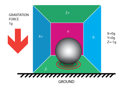
Accelerometer:
An accelerometer is a device that has the ability to measure and calculate accelerations in micro-movements. With in this device it is broken down to a simple structure that can detect three dimensions of acceleration. It is composed of springs holding together a centerpiece. When an acceleration is felt, a certain amount of voltage is generated though kinetic energy. The accelerometer has read and record the acceleration felt by the device.

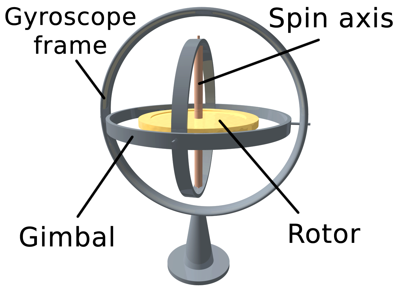
Gyroscope:
A gyroscope is a device that has the ability to measure and calculate angular acceleration based on its orientation. The angular acceleration can be calculated due to the structure of the gyroscope. Similar to the accelerometer volts are read when the internal parts of the gyroscope are displaced. However the structure varies from a basic accelerometer. There are disk and wheels whose axis is free to take up any orientation. For example if a force is felt on the positive x axis then the disk will rotate clockwise. This is important because due to the object that this robot will be balancing on, there are endless possibilities of motion.

The issue of the Accelerometer is that it lacks the precision and data that a gyroscope has in addition the gyroscope has an issue with calibration. By combining these two devices one could eliminate the issue of accuracy in data.
Accelerometer:
An accelerometer is a device that has the ability to measure and calculate accelerations in micro-movements. With in this device it is broken down to a simple structure that can detect three dimensions of acceleration. It is composed of springs holding together a centerpiece. When an acceleration is felt, a certain amount of voltage is generated though kinetic energy. The accelerometer has read and record the acceleration felt by the device.
Gyroscope:
A gyroscope is a device that has the ability to measure and calculate angular acceleration based on its orientation. The angular acceleration can be calculated due to the structure of the gyroscope. Similar to the accelerometer volts are read when the internal parts of the gyroscope are displaced. However the structure varies from a basic accelerometer. There are disk and wheels whose axis is free to take up any orientation. For example if a force is felt on the positive x axis then the disk will rotate clockwise. This is important because due to the object that this robot will be balancing on, there are endless possibilities of motion.
The issue of the Accelerometer is that it lacks the precision and data that a gyroscope has in addition the gyroscope has an issue with calibration. By combining these two devices one could eliminate the issue of accuracy in data.
Wednesday, April 11, 2012


Tuesday, April 10, 2012
Motors
Stepper Motor Basics - wiki link
what motor is right for our application??
size constraints - what dimensions will work?
torque spec constraints- how much torque do we need?
Small omni wheels in the size we want
http://www.robotshop.com/dagu-omni-wheel-41mm.html
1.6 inch diameter
.551 inch hole in middle
$3.60 each
Other similar sizes available
Stepper Motors
http://www.robotshop.com/bipolar-stepper-motor-10v-0-5a.html
Stepper Motors
http://www.robotshop.com/bipolar-stepper-motor-10v-0-5a.html
Monday, April 9, 2012
Chassis Materials Study
After stopping off in the machine
shop our team learned that the most efficient material to use to build our
robot would be Acrylic. The machine shop’s
capabilities to machine Acrylic are quite vast.
Acrylic bends when it is heated, to be shaped into any desired angle
with minimal machining, and it is very inexpensive to purchase in extruded rods
or sheets.


-These are typical examples of sheet acrylic, the material is available in a variety of colors
Acrylic’s
physical properties are perfect for our application because it is very easily
cut, it is more flexible than glass, it is more shock resistant than glass, it
is abrasion resistant, and it is easily cleaned. Our team will be able to utilize the ease of
cutting that the acrylic offers. We will
be able to take advantage of the laser cutter at the Drexel machining shop as
well as band saws and potentially hand saws.
We will also benefit greatly from the milling, drilling, threading, and
tapping.
The team
envisions the manufacturing process of the acrylic to encompass a large sheet
of acrylic to be fed into the laser cutter, where it will be cut to precise
dimensions. The pieces then will undergo
a series of drilling and tapping holes for screws to assemble the bot into a 3d
shape. The project is limited by the
capabilities of the laser cutter and are restricted to ¼ inch acrylic at the
thickest. The team is currently
researching the most efficient and precise ways to cut out the acrylic
components for the chassis of the robot as well as the most effective use of
either screws and/or epoxies to secure the components together.

This is an example of acrylic that has been cut with a laser cutter. The edges of the acrylic are smooth and precise, this could potentially be the best way to create a chassis with our specific design constraints.
A Curious Fabrication Technique

-http://lcamtuf.coredump.cx/rstory/
This image was pulled off of a blog by a polish engineer that fabricates robot parts using a cnc mill to cut precise molds to cast pieces in. The link above leads to his blog, which introduces his process in design, and is a very interesting read. He does a great job evaluating the different materials that he has available and the evolution of his projects can be directly related back to our project.
Designs and Information
Basic Designs:
From IEEE
The wheels are powered with NIDEC motors and micro-step controllers to achieve a 0.225 degree per step which resulted in smooth rotation.
The control system was run on a 16-bit microcontroller which received data from gyroscopes and accelerometers.


Robot Close up views:
note: dampeners
shocks and springs
ball rack


Microcontrollers
Microcontroller Basics:
Key aspects to keep in mind for the microcontroller: cost, ease of use, ease of programming
Arduino - most suitable controller platform
Useful links:
board constraints:
3 outputs for the wheel motors
multiple inputs: gyro, accelerometer, laser sensor ( to sense distance in a following mode)
Sparkfun - www.sparkfun.com
sparkfun 3-axis accelerometers
sparkfun 3-axis gyroscope
sparkfun arduino microcontrollers
IDEAS---
Microcontroller 1
problem: only two outputs
Microcontroller 2
6 inputs
6 outputs
32k flash memory
16MHz clock speed
input voltage 7V-12V
problems: no build in accel. and gyro
Accelerometers
Analog Devices' ADXL335 - Our 3-axis, analog accelerometer workhorse

| Accelerometer | Full-Scale Range | Interface | Axes | Maximum Bandwidth | Power Requirements | Bonus Features |
| ADXL335 | ±3g | Analog | 3 | 1600 (x/y), 550 (z) Hz | 1.8-3.6V, 350µA | Self test |
Pros:
- Very easy-to-use analog interface.
- 3-axis accelerometer - the first one on this list!
- Low-cost - when compared to the 2-axis accelerometers above, it's hard not to go with this one.
- The ±3g range should provide a good balance of range and resolution.
- Low-current consumption - 0.35mA!
- We can't say enough good things about this accelerometer - we've put it into all sorts of other products
Cons:
- The ±3g range can be limiting for some projects.
- Can only be supplied with up to 3.6V.
swarming - ultrasonic sensors necessary?
sparkfun ultrasonic sensor
Basic Microcontroller Block Diagram

Rezero
Notable other ballbot - Rezero
IEEE - Project Rezero: Ball Balancing Robot with style
( Ted Talks) Meet Rezero, the dancing ballbot-
Coding Nxt Ballbot with MatLab
Tuesday, April 3, 2012
Introduction
Ball Balancing Robots are a special class of robot characterized by their unique physical structure and method of locomotion. Ball balancing robots use an inertial measurement unit (IMU) such as an accelerometer to balance atop a spherical ball. Using three motors controlled by a microcontroller, the robot balances by righting itself as it begins to tip over. Similarly, the robot moves by achieving a set degree of inclination and rolling the ball beneath its body. To date, the most advanced ball balancing robot belongs to Eidgenossische Technische Hochschule Zurich. Their ballbot, Rezero, was designed for performance, maneuverability, and elegance.In building upon this design, our groups goal is to design and produce a smaller scale version of the ballbot. By simplifying the design and using smaller, more efficient hardware, we intend to create a version of the ballbot that is appropriate for mass production. Our bot will be roughly one third the size of the existing models and be made entirely out of cheap, accessible materials. The assembly of our robot will also be simple enough for a novice consumer to assemble. Finally, our robot will have the potential to be used in a swarm-type atmosphere where multiple ballbots can work together to perform tasks.
Subscribe to:
Posts (Atom)